OTIS (Omnidirectional, Three-Dimensional, Imaging System)
OTIS makes Photogrammetry Easy
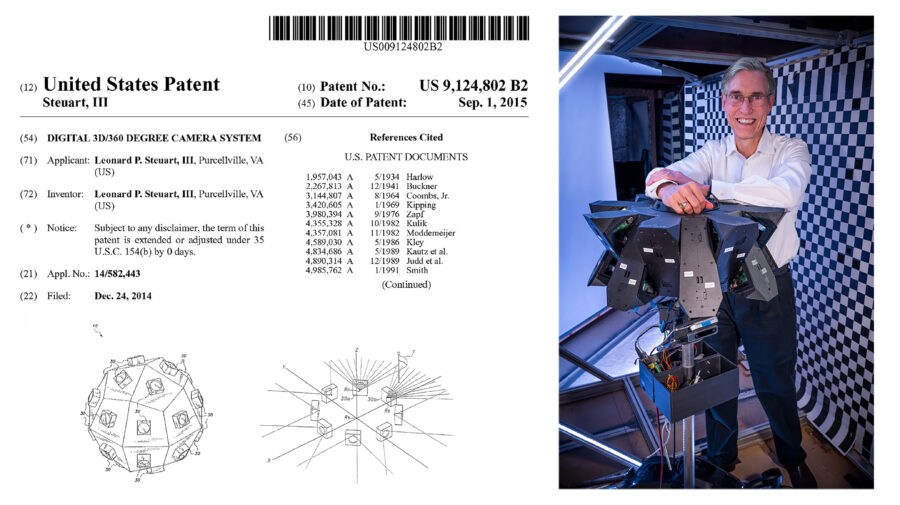
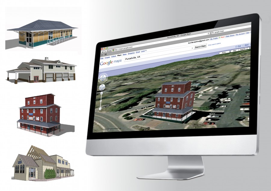
Practical photorealistic 3D capture and display has been an elusive goal since the first stereoscopic viewer was built in 1838. Because of the rapid evolution of digital camera technology over the last twenty years, automatic 3D capture and display is finally becoming a practical reality. OTIS combines our patented omnidirectional stereoscopic camera system with mature machine vision algorithms, standard 3D modeling tools, and current computer video display hardware (GPU). We improve the quality of our 3D output by enhancing camera optics and speeding up image capture. We use custom software to enhance the compatibility of our 3D output with mainstream 3D software like 3D Studio Max, Google Earth, and Google SketchUp.
Contact us if you would like early access to this emerging technology.
Omnidirectional Scene Acquisition IEEE Research Paper
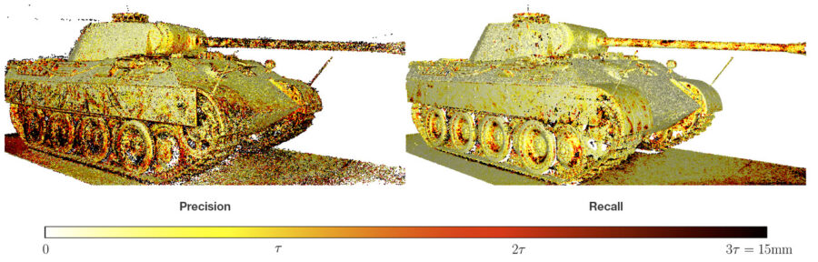
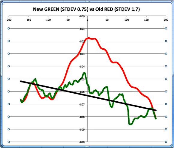
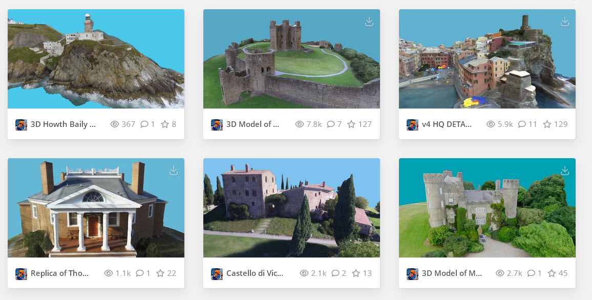
3D Photogrammetry Benchmarks Evaluate Precision & Details
2024: Reached #1 out of almost 500 in Tanks and Temples 2D to 3D benchmark
2022: Reached #1 out of almost 200 in ETH Photogrammetry 3D benchmark (2 years later that submission is #5)
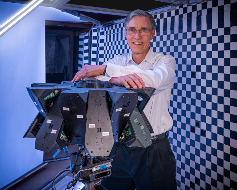
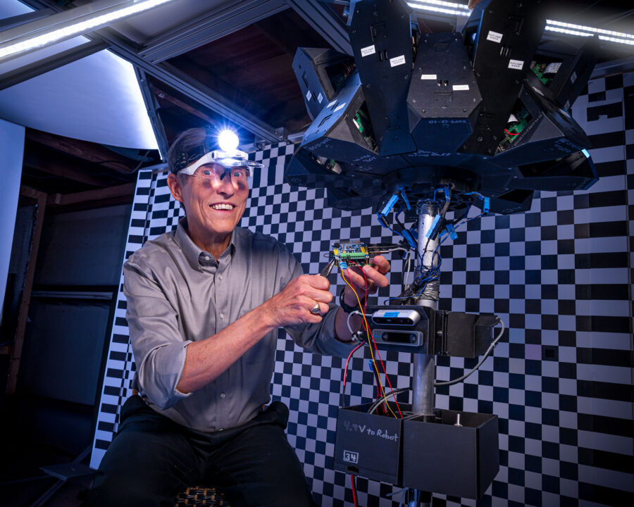
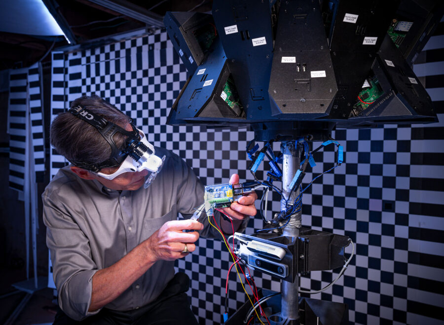
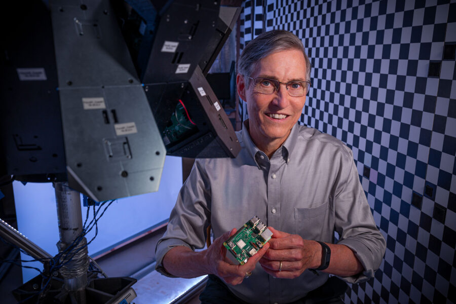
2020: Built & tested 32-camera prototype
2015: Discovered passive 3D scanning. Started using a DJI drone & Agisoft MetaShape to make 3D models.
2011: Began migration to Linux, OpenCL, and AMD APUs. An APU has the CPU & GPU on one chip to speed up communication.
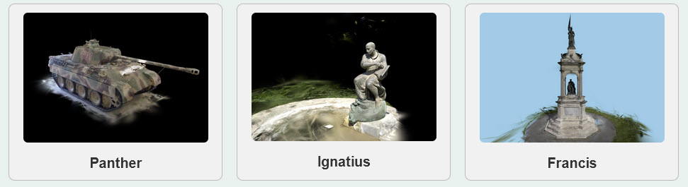
3D Model Gallery
Adapted GaussianSplat3D Viewer
Milestones of Steuart Imaging Systems:
2024: Our software reached #1 out of almost 500 in Tanks and Temples 2D to 3D benchmark
2022: Our software reached #1 out of almost 200 in ETH Photogrammetry 3D benchmark
2020: Built & tested 32-camera prototype. Realized that we needed to make custom software.
2015: Discovered passive 3D scanning. Started using a DJI drone & Agisoft MetaShape to make 3D models.
2011: Started migration to Linux, OpenCL, and AMD APUs. APUs share CPU & GPU memory efficiently.
2010: Continued building camera array prototypes and 3D software
2008: Programming team started using CUDA 1.0 to speed up image processing ~10x
2006: IEEE 3DIM Research Paper with University of Virginia
2006: Began developing skills in HDR photography
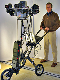
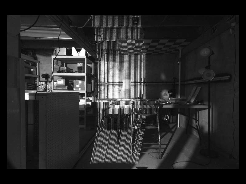
2005 to 2018: Built several original camera-array prototypes with cameras, lights, servos, and lasers.
2003: Filed 3D-360 Patent to fix limitations in panoramic photography (2D-360s)
1996: Started making panoramas (2D-360s) with Apple’s QuickTimeVR 1.0
1987 to 2002: Designed & managed computer & networking systems for up to 1,000 person company.
1984: Designed/Built 8-bit computer system (sensors, servos, and pump) with Motorola 6800 and code in assembly.
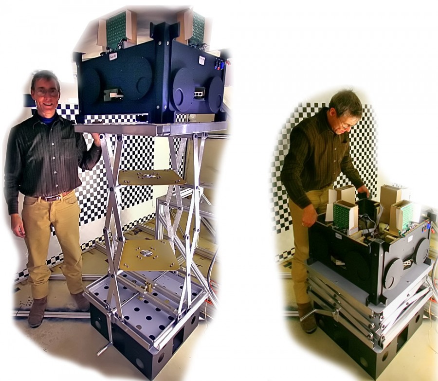
Behind the Scenes Gallery: 2024 with latest 32-camera array
Earlier prototypes:
Recent Posts
- 2024 Conference on Computer Vision and Pattern Recognition
- We Are #1 in the ETH 3D Software Benchmark
- Precise Calibration Is Essential for Good 3D Models
- Latest Example of 3D Scanner Noise Reduction
- Scanning Results Keep Getting Better
- First Results from New Proto-5A Scanner
- 9 Months of Software Enhancements Have Cut Errors in Half Again
- Progress Report: Sub-Pixel Upgrade Cuts Errors in Half
- Results from Summer 2012
- Making Good Photorealistic 3D Models from 2D Pictures
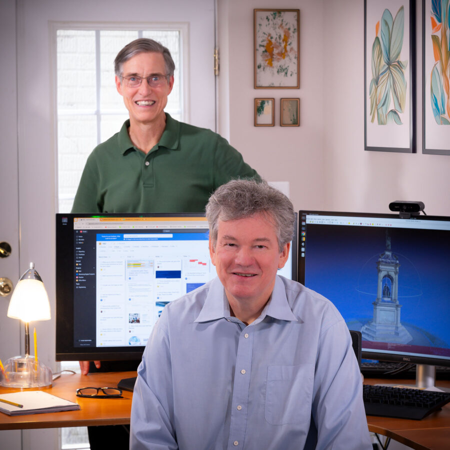
About the Team
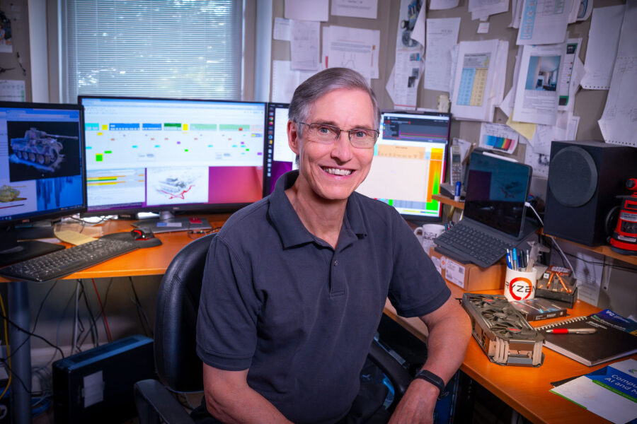
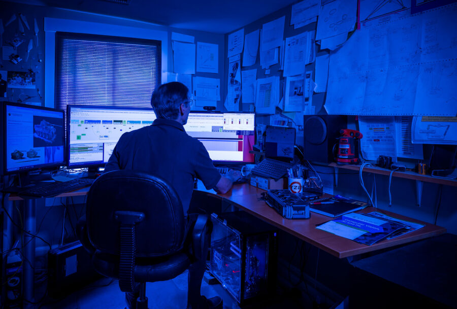
Skip Steuart The inspirational leader of the Steuart Imaging System’s team of programmers, engineers, scientists and mathematicians. Skip himself can be described as all of these things. He has worked tirelessly on the development of OTIS, his Omnidirectional, Three-Dimensional, Imaging System for over 20 years.
https://www.linkedin.com/in/3d360/
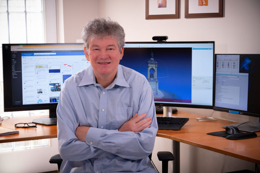
Tony Pike Cisco Systems Development Manager. Tony has worked as a Senior Software Engineer.
https://www.linkedin.com/in/tony-pike-7080141/
David Koller Stanford Computer Science Department & Computer Graphics Laboratory. David has a PhD in Computer Science from Stanford. His research activities are in the areas of computer graphics, visualization, computer vision, and human-computer interaction. He has been particularly interested in the acquisition, analysis, and interactive display of large graphical datasets. Some specific research projects, with links to papers and websites, are included on his page at Stanford:
https://graphics.stanford.edu/~dk/